
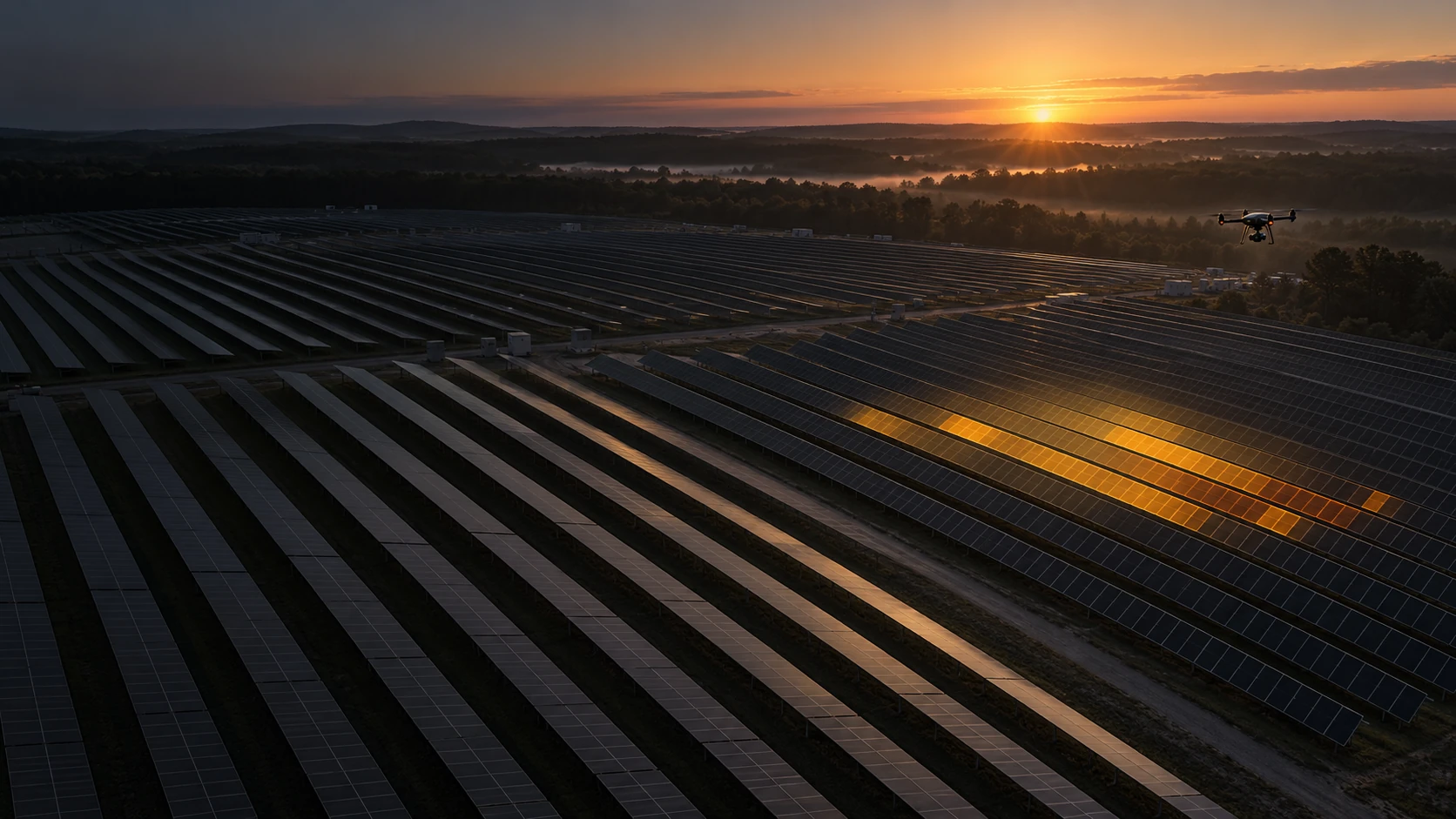
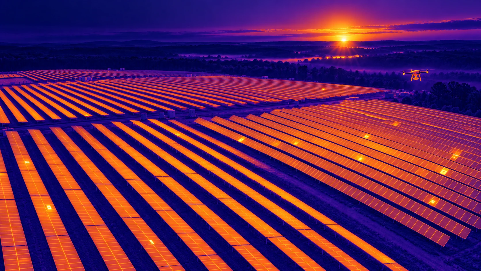
Illustrative solar field viewed in visible and thermal-style layers — Visible imageIllustrative solar field viewed in visible and thermal-style layers — Thermal illustration

Energy & infrastructure

ENERGY INSPECTION
& TECHNICAL
IMAGING.

Visible imageThermal illustration

Technical imaging for solar PV, buildings, wind turbines and power lines — connecting field observations with the decisions ahead.

Drag the slider or use the arrow keys to compare the two views.
All capabilities

From PV modules and building envelopes to turbine blades and transmission corridors: imaging and measurements built around the asset, the field conditions and the decision ahead.

Explore solar PV inspection

01 / Solar PV inspection — our core expertise

CONNECT THERMAL,
CELL-LEVEL &
ELECTRICAL EVIDENCE.

For plant owners, operators, EPCs and asset managers. We align infrared thermography, EL imaging and I–V testing with the question being investigated, from thermal anomalies to module condition and electrical performance.

01

Infrared thermography

Map thermal patterns across operating PV assets and identify anomalies for technical review. Acquisition is planned around site conditions and the inspection objective.

Deliverables

Thermal and visual imagery, with anomaly documentation and reporting defined in the project scope.

02

Electroluminescence imaging

Examine cell-level features and indications of damage that may not be visible in standard photographs. EL acquisition is coordinated with the site’s electrical team.

Deliverables

EL image sets with module identification and interpretation requirements agreed before acquisition.

03

I–V curve testing

Measure the electrical response of selected modules or strings to support performance assessment and investigation of suspected issues.

Deliverables

Test records, measurement conditions and technical evaluation within the agreed test scope.

02 / Building envelope & roof thermography

SEE HOW YOUR
BUILDING PERFORMS.

Thermal imaging for building owners, facility managers and property professionals. Investigate insulation-related patterns in walls and façades, and screen suitable roof systems for thermal anomalies associated with possible retained moisture.

01

Building envelope

Examine thermal patterns at wall assemblies, junctions and openings to guide investigation of possible insulation gaps and thermal bridges.

02

Roof thermography

Assess roof-system suitability and survey conditions before screening for suspected moisture-related anomalies. Confirmation is separately scoped.

03

Documented findings

Connect thermal and visual images to building locations, acquisition conditions and recommended follow-up.

Explore building & roof thermography

03 / Wind turbine inspection

A CLOSER LOOK AT
THE BLADE SURFACE.

Drone-based visual acquisition for wind turbine inspection programs. Image coverage and flight trajectories are planned around the client’s inspection requirements and coordinated with the site team.

01

Planned coverage

Agree turbine identifiers, blade views and acquisition requirements so image sets can be incorporated into the client’s inspection workflow.

02

Site coordination

Coordinate turbine stopping and blade positioning with the operator. Field planning accounts for access, weather and the approved capture procedure.

03

Organized image delivery

Deliver visual image sets indexed to the agreed asset structure. Engineering assessment and defect classification are separately scoped when required.

04 / Power line & corridor imaging

DOCUMENT THE ROUTE.
KEEP THE CONTEXT.

Imaging and data acquisition for electrical transmission lines and their surrounding corridors. A route-based approach helps clients connect field imagery to the locations and assets they need to review.

01

Route & coverage planning

Translate the corridor extent, access constraints and client requirements into a defined field acquisition plan.

02

Line & corridor imagery

Capture agreed views of line assets and the surrounding route to support the client’s review and analysis process.

03

Traceable handover

Organize imagery with the location references, naming and file structure agreed for the project. Analysis requirements are defined separately from acquisition.

One delivery discipline

FROM FIELD SCOPE
TO USABLE OUTPUTS.

01

Define the question

Identify the assets, coverage, access conditions and decisions the work needs to support.

02

Plan the acquisition

Agree methods, operating conditions, site coordination and data requirements before mobilization.

03

Capture & check

Acquire the required imagery and measurements, checking coverage and data quality throughout fieldwork.

04

Deliver in context

Organize outputs for the client’s workflow, with interpretation and reporting where included in the scope.

Start with the asset

WHAT DO YOU
NEED TO KNOW?

Share the asset type, location, project scale, intended schedule and required outputs. We’ll define an acquisition and delivery scope around your objective.

Discuss an energy project info@thetaimagingservices.com